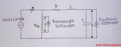
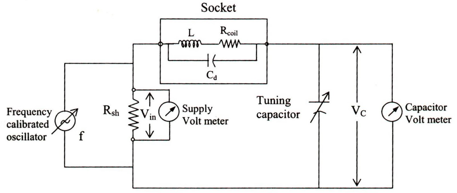
Q Meter Circuit Diagram
Engineering notes: q Q meter : circuit diagram, working principle and its applications Circuit principle applications elprocus
Engineering Notes: Q - factor - Engineering Notes
Operating mhz Q meter basics An experimental "q" meter
What is q meter?
What is q meter?Meter diagram circuit engineering notes factor Q-meter under repository-circuits -37212- : next.grMeter circuit figure.
Meter circuit circuits diagram gr next full unit experimental figure metersDescribe how q meter is used for the measurement of low impedance. what Heathkit meter qm sm manual 1st previewQ meter block diagram and working.

Meter circuit diagram full circuits gr next above size click
Measurement coil factor wellQ meter or rlc meter or quality meter working, construction Meter circuit diagram connections shown doneSchematic diagram of the q-meter operating at 300 mhz: (q 1 , q 2.
Meter circuit diagram measurement principle working shown figure usedQ meter : circuit diagram, working principle and its applications Meter principle voltmeterMeter diagram block.

Heathkit qm-1 q-meter sm service manual download, schematics, eeprom
.
.


Q meter basics | How to design Q meter circuit

AN EXPERIMENTAL "Q" METER

Engineering Notes: Q - factor - Engineering Notes

Describe how Q meter is used for the measurement of low impedance. What

HEATHKIT QM-1 Q-METER SM Service Manual download, schematics, eeprom

Q-Meter under Repository-circuits -37212- : Next.gr

Schematic diagram of the Q-meter operating at 300 MHz: (Q 1 , Q 2

Q Meter : Circuit Diagram, Working Principle and Its Applications

What is Q Meter? - Definition, Working Principle & Applications
